This is a passive mixer with a specific purpose; to test the musical usability of per-channel stereo auxiliary send pan controls. But it builds on circuit blocks that are applicable to any passive mixer you might want to build.
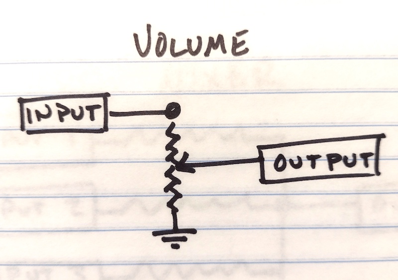
The first block is an input jack and a volume control. One of the most basic and important circuits! A 10K audio taper potentiometer works well for a passive mixer.
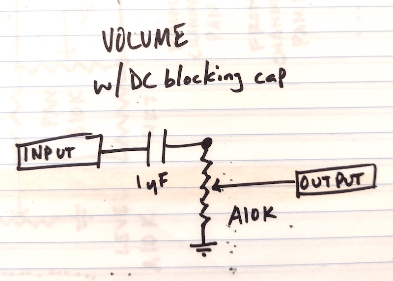
I did not add DC blocking to my mixer, but if you wanted to you could do it like this.
The second block is the pan control. I got this block from Elliott Sound Products; they have a ton of great information on their site. What’s going on is two voltage dividers (like volume controls!) wired up in a specific and inversely correlated way. (“L” and “R” output are drawn arbitrarily in this drawing; just be consistent!)
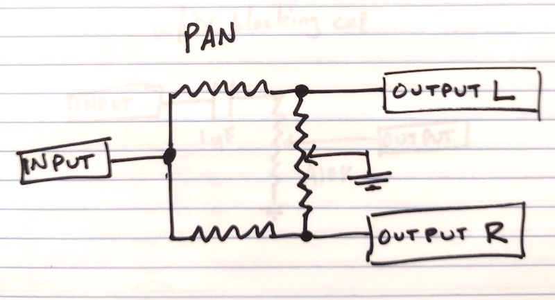
The fixed resistors (horizontal in this drawing) form the top leg of each divider. The bottom leg is formed by the portion of the pan potentiometer (vertical) between the fixed resistor and ground. As pan pot lug 2 is turned toward either resistor, the ratio of the top leg to bottom leg increases, so the signal level decreases.
Note that this means that the knob you eventually put on the potentiometer will point toward the signal that is being lowered more than the other! (This is the reverse of a volume pot, where the knob points toward higher level.) I got this backwards the first time I wired up a pan pot because I hadn’t thought it through.
The value of the fixed resistors affects the taper of the pan from side to center. I did some math and settled on 4.7K fixed resistors and a 10K linear taper pan pot. Smaller resistors will result in more signal being passed when the pan pot is near the center. I was aiming for my preferred setting in Reaper for mixing, which is a -3 dB pan law. These part values give about a -3.5 dB pan law.
The third and final block is the actual mix block. Every incoming signal goes through a resistor; together, the resistors average out the values of all of the incoming signals and pass the result to the output jack.
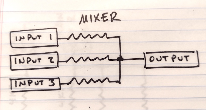
This block is probably the weakest point in a passive mixer; you’re trading off signal isolation with signal loss and thermal noise and there isn’t really a win-win, it’s more of a pick-your-poison. I wouldn’t go any lower than 1K resistors, which would provide lower noise but more risk of signals interfering with each other. On the other side, I wouldn’t go higher than 10K, as the isolation you gain beyond that value isn’t worth the noise and signal loss. I used 4.7K in my mixer simply because I had chosen that value for the pan controls, so I had a bunch of resistors in the right range at hand. I used 2.2K in a different matrix mixer I built, which seemed to work fine. I would use either value again, or a 5.6K, or a 6.8K, in a future passive mixer without much thought.
Here’s everything connected as I did in the crayon tin mixer. Each of the three input jacks is connected to two level controls (left of the orange strip); main (pictured) and aux (not pictured). Each level control (six total, three main and three aux) feeds a pan control (between the orange and pink stripes). Pan controls have two outputs, conventionally “Left” and “Right,” so the crayon tin has twelve pan outputs feeding four output jacks: Main L, Main R, Aux L, Aux R (to the right of the pink stripe). That means each output jack’s mixer is mixing three signals (not all pictured), relating back to the three inputs. Hopefully that makes sense! Each input has a path to all four outputs.
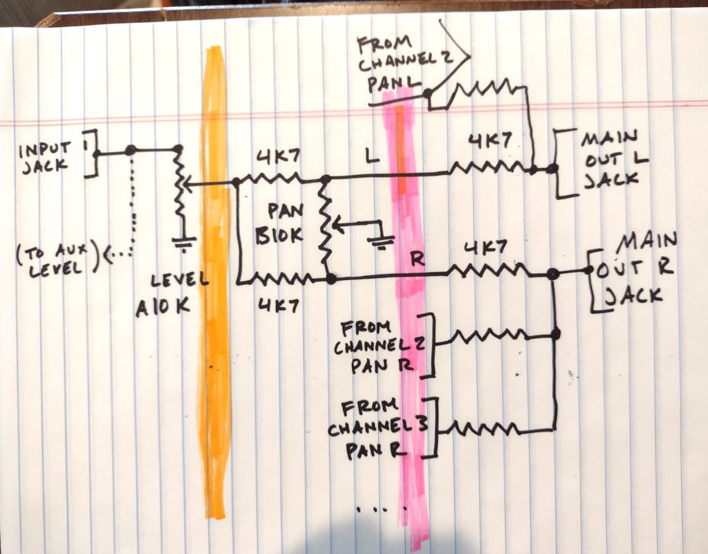
All that is pictured here is:
- One input jack (out of three on the crayon tin)
- One main level control (out of three, plus there are three not-pictured aux level controls)
- One main pan control (out of three, plus there are three not-pictured aux pan controls)
- The two main output jacks (the aux output jacks are not pictured)
But what’s missing is the same as what’s shown, just repeated!
You can combine and multiply these blocks as you like to come up with your own mixer for your own signals. The more channels you add, the worse your signal loss and signal-to-noise ratio would be. Depending on your tolerance for noise, you might go as high a six input channels, maybe, with pretty good results. Or more; maybe you like noise (sometimes I do!)
If you wanted to make this an active mixer, the place to do it would be at the actual mix stage, between the mixing resistors and the output jacks. You only need one opamp per output jack (so, half of a dual opamp like a TL072! A sole TL074 could have made the crayon tin active in this way!!) and the circuit is very simple, you can look it up anywhere; search “unity gain mixer schematic.” After doing that, in theory you could buffer the inputs, but it’s overkill in my opinion, unless you’re a scientist about your music (congrats for real), or you’re plugging your guitar into the mixer with no pedals on and no Boss or other buffered pedals on your board.