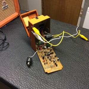
I spent the afternoon installing sockets for some components in a DS-1 pedal so that I can easily experiment with some mods, turning it into a DS-1 laboratory of sorts.

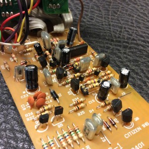
You can see the sockets well in the photo below. They’re the little black legs on the PCB that components can just pop into, instead of soldering components directly to the board. There’s a transistor labeled “Q2” close to the center of the frame; look to the right of that for two socketed resistors.
No component values have changed, yet; I don’t have a real amp at home to test things on, just a tiny practice amp that’s enough to let me know I’m passing signal :-) Video to follow once I figure out some sounds I like.
I socketed:
- R6 and R9 (input transistor bias and gain, respectively)
- R7 (opamp gain)
- Edit 2015 Nov 14 – C5 and C7 (different values than the MIJ DS-1s, as described by Brett Miller. I left C8 alone, though he includes it in his MIJ mod, because I like the cutoff frequency created by the stock MIT DS-1 value for C8)
- D4, D5 (the hard-clipping diodes), and C10 (low-pass filter)
- R16, C12 (the low pass filter side of the tone stack), C11, R17 (the high pass filter side of the tone stack), and R15 (in series with the high pass filter side of the tone stack, reducing its output)
- R18 (a resistor in series on the output; just cuts output, from what I can tell, though now that I type this I realize it may be part of biasing the Q7 transistor)
That amounts to two gain stages, the hard-clipping stage, three post-gain filter sections, and possibly the output level. I plan to jumper all of the socketed components from the output back to the first gain stage to hear what that sounds like, see what improvements can be made (likely the Jack Orman phat mod), and build back toward the output from there stage by stage.
I’ll be experimenting with various hard-clipping options as well, with the goal of finding a few good ones to put on a switch.
Good times, and no soldering iron burns today!
