DS recording live as a trio for the first time today.

Guys played well, I need a few more takes to really nail it.
DS recording live as a trio for the first time today.
Guys played well, I need a few more takes to really nail it.
Couple pics from Scott & Katie’s visit this weekend; bass clarinet recording and rocking with Approach. Recording continues today.


(Full-size version at I Heart Local Music, photo by Ailecia Ruscin)
Drew and I reamped all the Mars Lights bass tracks Friday night. Sounded pretty huge.
We were short on good mics for bass cabs when we were doing the main tracks, so we recorded a DI bass signal. Friday we ran that signal back out from ProTools through the bass gear.
Not everything in the picture was on. Signal chain was ProTools > Empress Compressor > Falcon Heavy > LS-2 (signal split) > two amps: Music Man 65 and Traynor Bass Master.
I also got a vocal track down – first one since before Thanksgiving, when I got sick – so massive progress on the double LP this week. \m/
My bass rig is now back at home for recording h&s tracks.
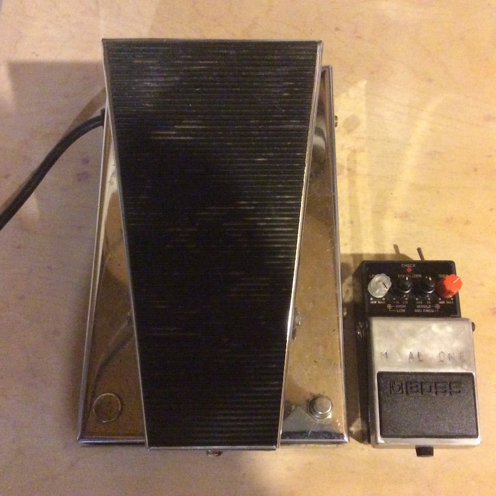
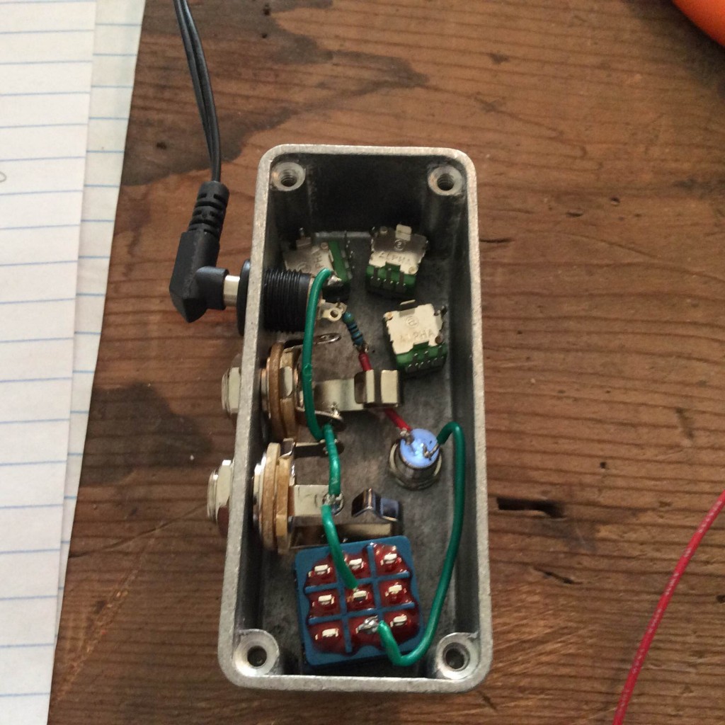
Cole gave me some cool vintage pedals to fix the other week, and I learned a lot working on this old Morley WVO Wah-Volume. As he gave it to me the wah effect worked, but the volume control didn’t.

Both effects are controlled by photoresistors. In the image above, you can see them peeking out from under the black hood that’s taped to the green PCB. These are variable resistors that serve the same function as potentiometers (or “knobs”).
Sidenote; you can see how the Morley company used one PCB, enclosure, and drilling template for several different models of pedal to save on production costs. Notice the empty pads where additional components could go on the PCB, and the metal buttons filling unused holes in the enclosure like the one below.

Both the wah and volume circuits are based on light from the little bulb on the left side of the photo above hitting those photoresistors (or not). (The bulb is on the other side of the bracket near the red electrical tape.)
The heel of the treadle is connected to that flap of black fabric. In the heel-down position, the fabric covers the opening of the hood (just heavy black paper and black masking tape); the photoresistors are in near-total darkness and therefore near their maximum resistance. This is shown in the photo below.
As the player pushes the treadle forward toward the toe-down position, the fabric flap is pulled back, gradually allowing light from the bulb to reach the photoresistors and decrease their resistance. The photo above shows the toe-down position.

So Cole’s pedal was, electrically, perfectly fine. The fabric flap had come un-taped from the inside of the enclosure (40-year-old masking tape will do that), so light was reaching the volume circuit’s photoresistor no matter the position of the treadle. Re-taping the flap to the enclosure solved the issue.
I literally fixed a pedal with duct tape.

The bottom plate of the enclosure even has some reflective paper taped to it, to reflect the bulb’s light and strengthen the effect (see above).
These old chrome Morleys are built like tanks, sound great, and have an extremely high cool factor. They’re also heavy, and giant; see below, next to a standard Boss pedal for scale.
TKTK

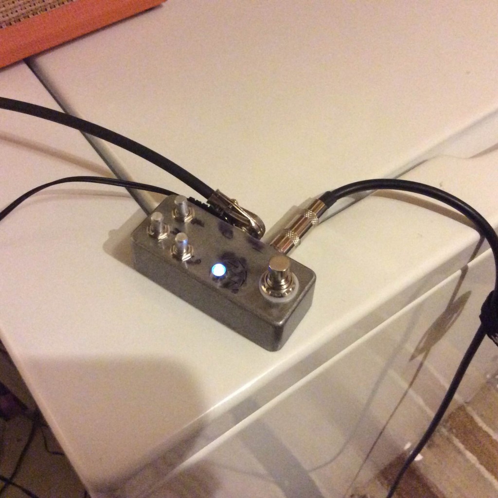
This afternoon I’ll be building the first Giambattista Tremolo in a one-off custom enclosure courtesy of Seth M Jones. I did the LED and bypass wiring yesterday to give myself a head start.

The Giambattista is based on the old Jordan Vico Vibe (and a layout by Nicholas Kula). I’ve added a JFET boost and volume control on the output, which others have done with this circuit. I’ve also moved the bias (which affects the pulse width) control to the outside of the enclosure, and added a fast/slow rate range toggle, which I haven’t seen done before.
The Vico Vibe is a great, vintage-sounding tremolo, but the knock on it is that the rate range is fairly narrow (and quite fast, with stock components). The Giambattista, with its fast/slow ranges, will go from faux-ring modulation fast to obscenely slow.

More videos on the way once it’s done.
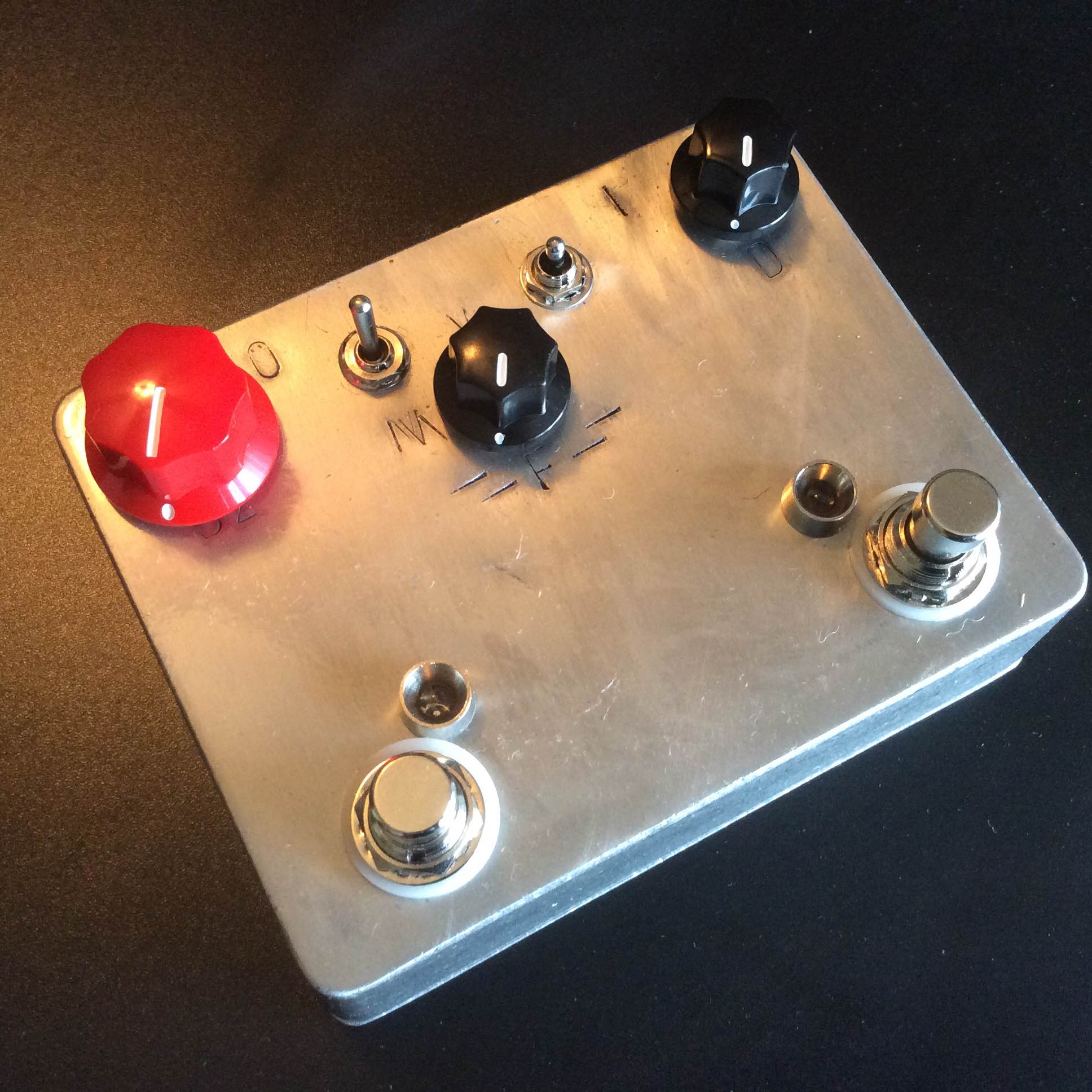
The “D2” label will be moved down for future units, of course. I wasn’t thinking about over-sized knobs when I stamped this first enclosure.
“M” will become “M2” (since the mids switch is only available when the D2 channel is engaged) and the unlabeled switch probably needs a “C” for clipping.
Sounds righteous, nonetheless! Psyched to get it integrated into my Mars Lights rig.
I figure the main channel will replace my VFE Triumvirate for always-on boost & slight clipping duties, and channel 2 will replace the EHX Bass Big Muff Pi for heavy parts. I still love those pedals, this will just free them up for other uses, probably recording for the Triumvirate (where its flexibility really shines) and maybe suuuuuuuuuper-heavy parts for the Muff.
Demo videos & pre-ordering form forthcoming.
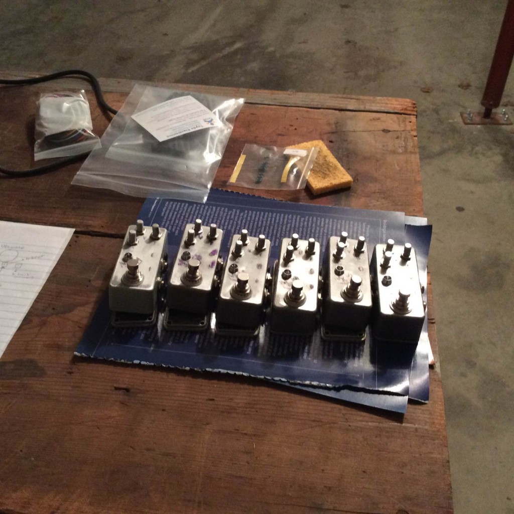
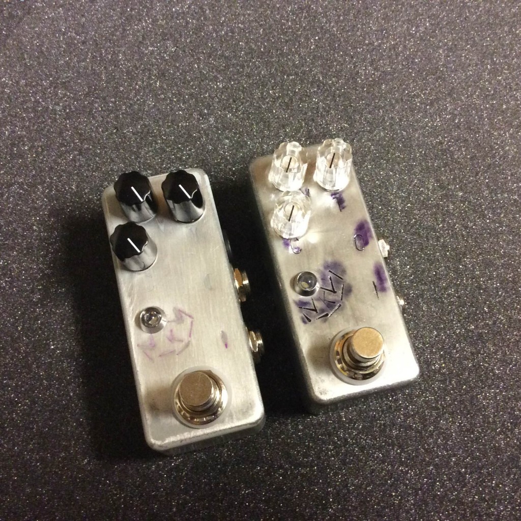
Over the past two weekends I’ve made progress on my first run of six Kingman pedals, and have finished the first two. I know #0002, the one I’m keeping, will go into immediate use as Mars Lights continues to record our double LP.
Last weekend was given over to figuring out how to finish the enclosures. I tried various combinations of paint, stamping, Sharpie, dry sanding, wet sanding, and clear coating.
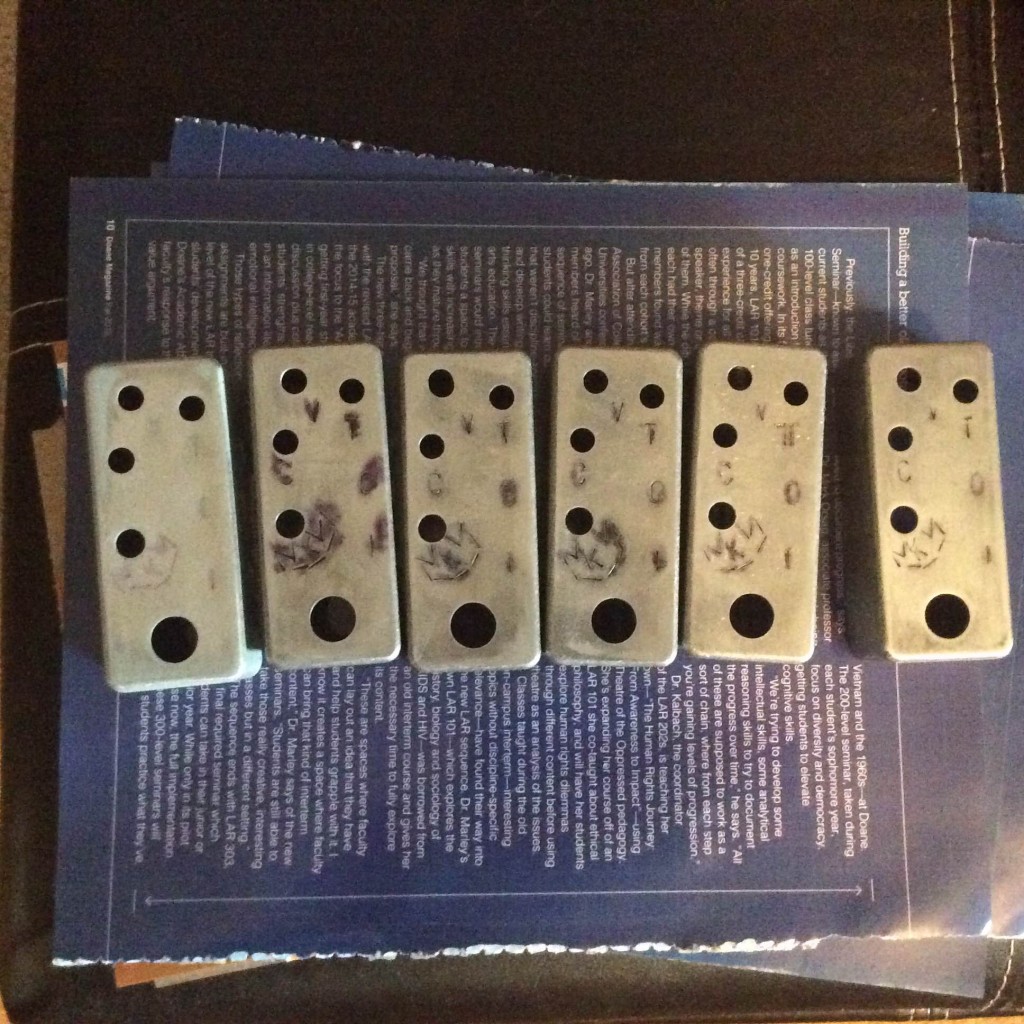
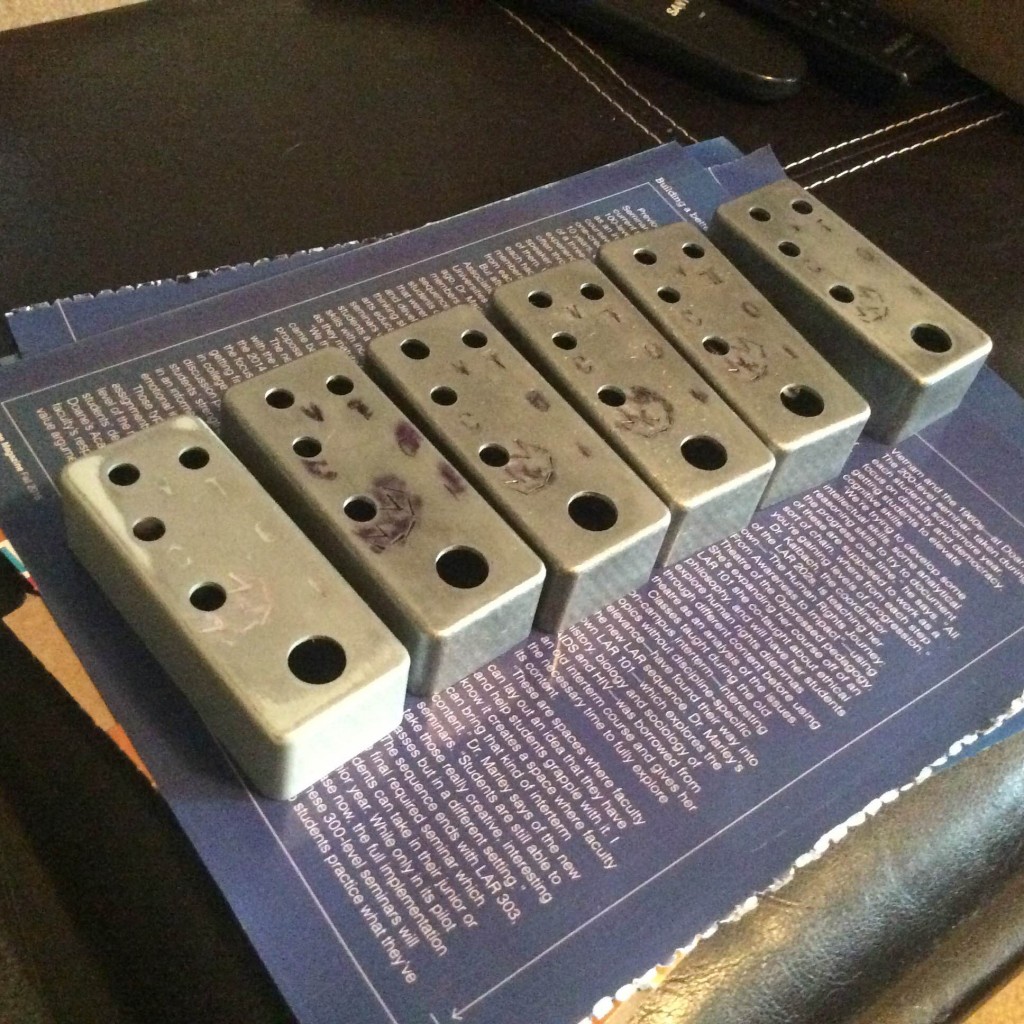
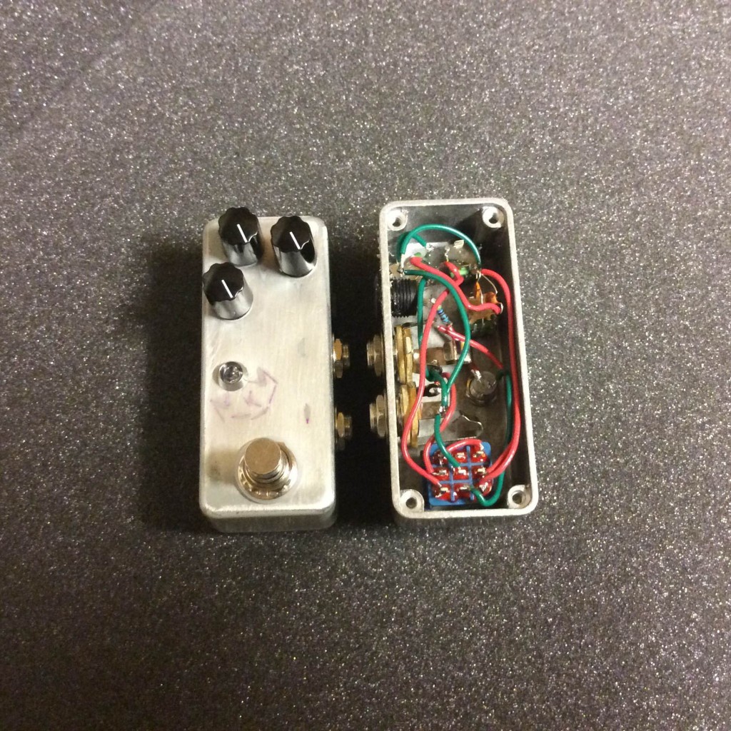
Simple as the Kingman circuit is, there’s no circuit board; just parts mounted to the enclosure, point-to-point wiring, and two capacitors.
Yesterday I started wiring. It’s not the prettiest but the connections are solid and it gets the job done. No one can hear my wiring!
The first one took two and a half hours, but it worked on the first try. I consider that a win.
After getting #0002 running (I numbered based on the enclosures. Wanted to do something special with #0001 and thought it would benefit from me making and correcting any wiring mistakes on my own) I wired #0001 up today. #0001 is the only enclosure I painted and will be the only one with black knobs. Future Kingmen will look more like #0002 with the clear knobs, but without the purple smears. I learned how to fix that, but thought that since purple is a royal color I would leave mine with the weird blurs.
Like I said, not the prettiest at all. Neither were a lot of great-sounding vintage pedals! I appreciate today’s beautiful PCB and wiring jobs as much as the next guitar player, but they’re not necessary for a circuit to do its job.
What have I learned?
My BuildYourOwnClone.com Confidence Boost kit came together in a snap, no problem. It lives, it breathes, it boosts!

Next up, a Large Beaver (which will replace my EHX Bass Big Muff Pi) built to Triangle-era specs. Might be a couple weeks before I get to that, but I’m pretty psyched about it.
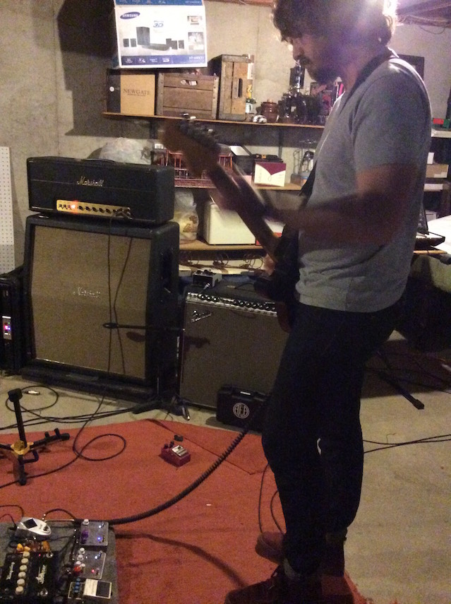
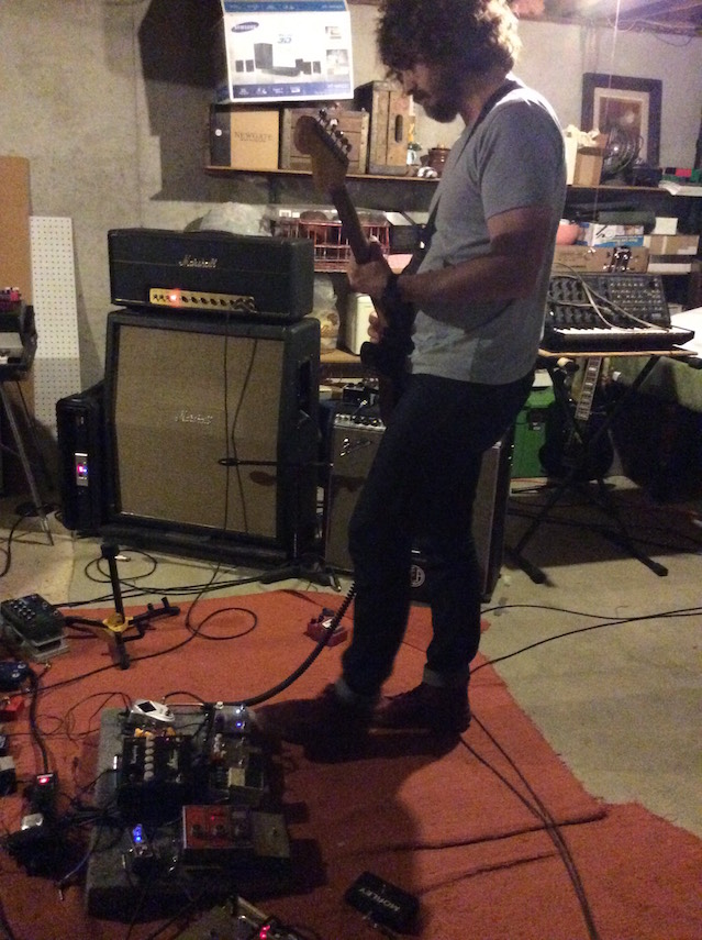
A couple months ago Drew and I went in together on a late 1970s Soundtracs FME mixing console, based on Duane’s recommendation. We scored a good deal on eBay, carefully dragged the 225-pound unit (console + road case) down to the basement, and this past Monday I got to work with it for the first time.

First I tested each channel with one signal, listening and compensating for any differences among them. These circuits are 35+ years old, and have drifted a bit; to get each channel to sound the same I used preamp gain settings as much as 11 dB apart, EQ adjustments of -1.5 dB to +3 dB, and levels as much 4.5 dB apart. That took all morning, and while we’ll tweak it as we continue to use the board, those settings will be a foundation we can start mixes from in the future.
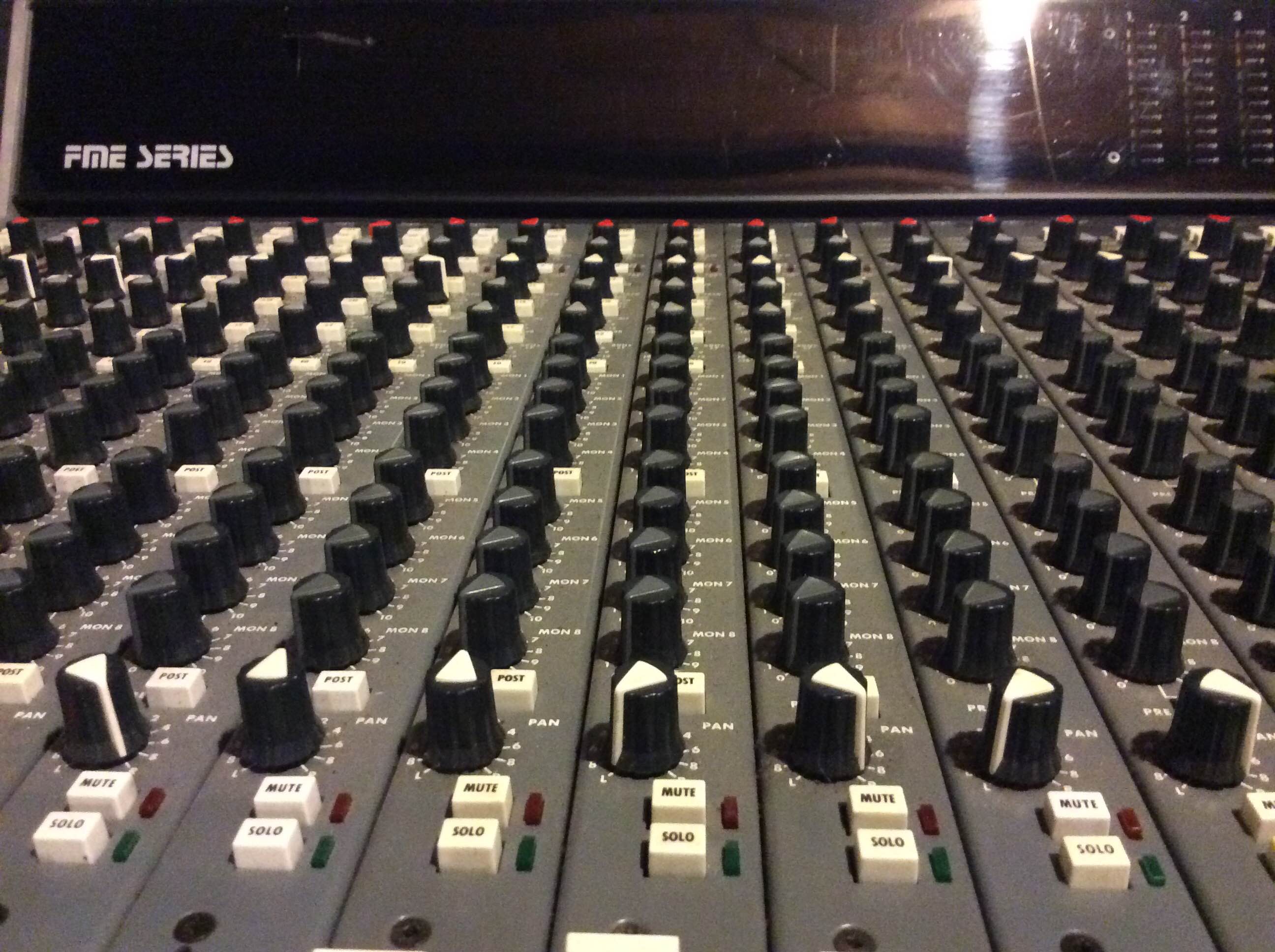
Then I actually mixed a five-song project for upcoming release on MFR. I’d already gotten the mixes to a state I was happy with in ProTools, so I was just routing those tracks through the console and back into ProTools in stereo, making fine adjustments.

Mixing on the Soundtracs was brilliant; revelatory, really. Even at levels below clipping, the preamps subtly compress and add harmonics in a beautiful way. The EQ was the best part, though. In ProTools, I’ll spend weeks on a mix agonizing over tiny changes in EQ, trying to get things to sound their best. On the console it’s simple and natural to turn up the level, sweep the frequency for the range I want to affect, and bring the level back down until I’ve achieved what I want to hear.

It wasn’t cheap, but even so this piece of gear was well worth it for us, and offers good bang-for-buck in that it will substantially improve every mix we do (think: new Mars Lights LP, new Dark Satelliets LP, Cory’s solo project, and more) from now on. And it’s fun to use.
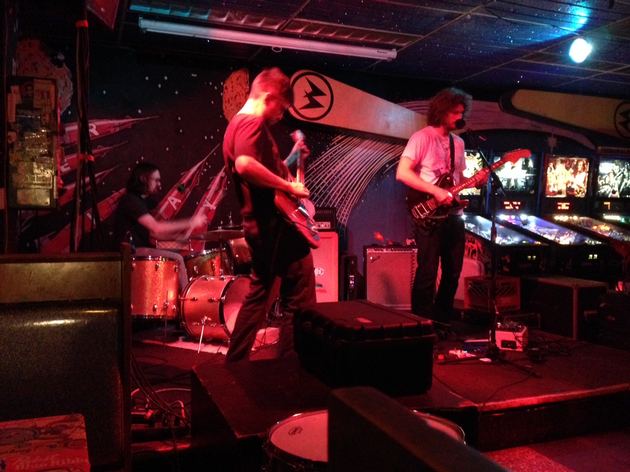
As a bonus, here are some pics of Drew pole-dancing in Wichita Friday night, then deciding to sit on the floor and enjoy the music, at the Mars Lights / Vehicles / Admirals show.


While I’m at work on mr|ten (out Friday 19 September) recording with Cory (yesterday) and mastering (today), Jill’s making hats and rocking her new Mars Lights tee pretty hard.

Maintain the rock and you don’t stop the rock, and I’ll keep on those hot new jams.